Difference between revisions of "App Note 1242 - Google Dashboard"
(Created page with "This App Note describes how to implement a web temperature dashboard for Arduino Ethernet. It is intended to show you how the Memory-Map concept works in the practice and the...") |
(No difference)
|
Latest revision as of 21:12, 29 March 2018
This App Note describes how to implement a web temperature dashboard for Arduino Ethernet. It is intended to show you how the Memory-Map concept works in the practice and the way in which it can help you to improve your Arduino projects with some few simple modifications.
Contents
Overview
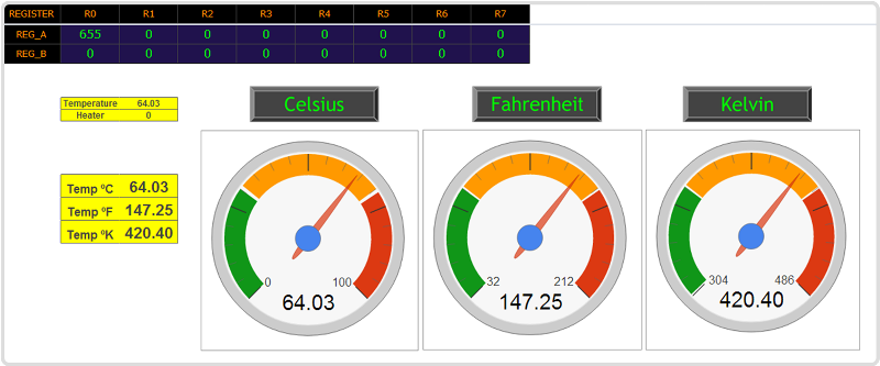
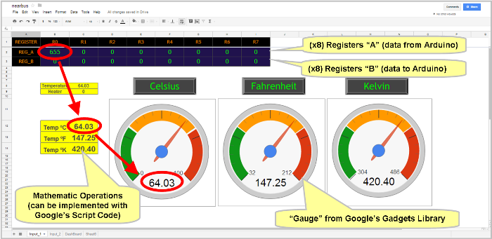
The system shown consists of an Arduino with a temperature sensor (eg. a LM134 lineal temperature sensor IC) connected to the NearBus Connector through internet to display the temperature value in a graphical way using the Google Spreadsheet Web App (as shown below).
How does it work?
As detailed in the overview section the NearBus system has two working modes, the VMCU (virtual microcontroller unit) mode and the TRNSP (transparent) mode. In this example we are going to use the TRNSP mode.
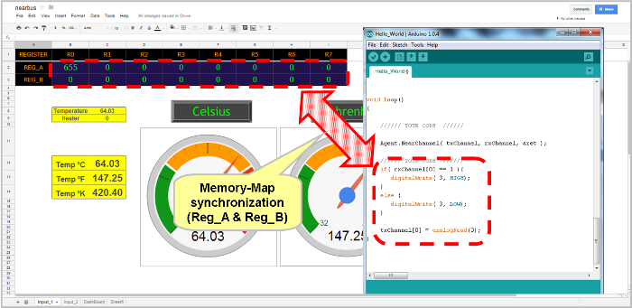
Under the TRNSP mode the NearBus system works replicating two groups of 8 registers each (Reg_A and Reg_B) in a periodic way :
Reg_A: Data sent from Microcontroller to the Cloud.
Reg_B: Data received in the Microcontroller from the Cloud.
In others words, the TRNSP mode can be understood as a RPC (Remote Procedure Call) or function call, that you make in your Arduino code to execute it in the cloud (as a spreadsheet formula or script), obtaining a result, and then using it in your Arduino code.
The most powerful feature of NearBus is the extremely easy way in which this complex process can be achieved. Including a single line in your code (a function call) you will be able to synchronize the register blocks (8+8) with the Google Cloud and then access them from a simple spreadsheet table (2 rows 8 cells).
So, under the TRNSP mode, changing a value in the spreadsheet replicates this value in the Arduino's memory (and vice versa) in a periodic way.
STEP 1 - Setup a New NearBus Account
To setup a new account in the NearBus Connector, please follow the steps 1 to 5 in the Hello World [1] example.
IMPORTANT: Remember that this example works in TRNSP mode so you should uncheck the VMCU option when configuring a new device (Step 2) in the NEW DEVICE configuration screen (VMCU is the default option).
STEP 2 - Setup the Google Channel in NearBus
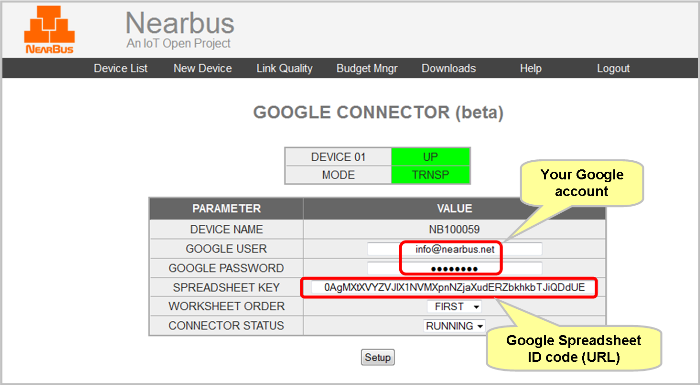
To activate the Google Channel in your NearBus session, you should configure the parameters shown below. To access this configuration table select the GOOGLE CONFIG option in the drop down menu (on the DEVICE CONFIG screen).
NOTE: Take into account that for this step you will need a Google account. We recommend defining a new Google account for this environment if you already have one.
Google User: Your Google user name.
Google Password: Your Google user password.
Spreadsheet Key: Copy the Spreadsheet_ID and paste it into this field (*).
Worksheet Order: For this first example should be FIRST
Connector Status: Allows you to Turn On or Turn Off the connector. Set it to Running.
(*) The following step will show you how to get this ID from Google.
STEP 3 - Configuring the Google Spreadsheet
Login your Google account, select the Google Drive option in the menu bar and create a new spreadsheet.
Create the Memory-Map table, this table should be defined between the cells A1 to I3 (3 rows of 9 columns) and should match exactly as the following format (of course you can change the colors :)
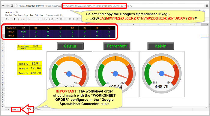
The spreadsheet is identified by the Google Apps through a Spreadsheet_ID code, a long alphanumeric string (Base64 encoded) that follows to the keyword "key=" in the browser's address bar. You should identify it and copy and paste (be careful to include all characters). The following picture shows where this ID is located
IMPORTANT: The different worksheets in a spreadsheet are identified by the physical order (from left to right) so you should be careful matching the worksheet order with the configuration chosen in the field WORKSHEET ORDER (in the GOOGLE CONNECTOR screen).
STEP 4 - Write the code into your Arduino
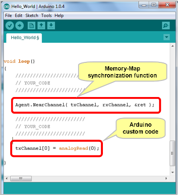
For this example we use a simple analogRead() as shown below:
A_register[0] = analogRead(0);
Additionally you should include the NearBus service call (in some point of the main loop() function :
Agent.NearChannel( A_register, B_register, &ret );
NOTE: Remember that NearBus offers you 2 groups of 8 registers each that are synchronized in each exchange operation and you can use them freely in your code.
| GROUP_ A | GROUP_ B |
|---|---|
| A_register[0] | B_register[0] |
| A_register[1] | B_register[1] |
| A_register[2] | B_register[2] |
| A_register[3] | B_register[3] |
| A_register[4] | B_register[4] |
| A_register[5] | B_register[5] |
| A_register[6] | B_register[6] |
| A_register[7] | B_register[7] |
STEP 5 - Define the math formulas in the Worksheet
Create the dashboard using the different gadgets that Google offers to you (Gauges, Charts, etc, form more detail see insert-> gadgets in the spreadsheet menu bar).
The Memory-Maps table works as a simple spreadsheet table with the following characteristics:
Each "x" seconds the NearBus will update the Reg_A with the values sent by the remote Agent (eg. Arduino) and then will read the value stored in the Reg_B (and return them to the remote Agent). As we mentioned before the system works as a typical function call from the Arduino code point of view.
NOTE: Because Google's Cloud Infrastructure impose some limitations in the service quota in order to avoid system overload, the synchronization period is limited to 10 seconds.
NOTE: In order to avoid upgrade the REG_B in the NearBus Data Base you should fill all the REG_B cells (from B3 to I3) to null (case sensitive). This feature will allow you to avoid data collision when using the Google Connector and REST API simultaneously.
STEP 6 - Wire your Arduino
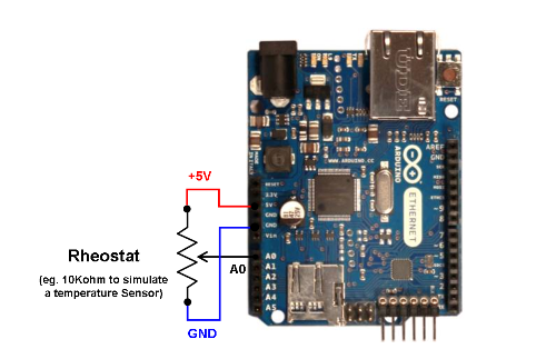
In this example we replace the temperature sensor (an LM134) for a simple rheostat connected to the A0 pin in order to test the system. The following picture shows the trivial configuration required in order to emulate the temperature sensor (the rheostat can be of any value between 10K and 100K ohm).
If you want to try more features available in the functions drop-down menu please refer to the HELP [2] section for a detailed description.
If you are interested in knowing more about this App Note please contact us at: info@nearbus.net
