Nearbus Waterproof
Nearbus Waterproof is a small implementation of the basic NearBus Ethernet device (developed to the Arduino Ethernet board). This device has been designed be installed in outdoor environments allowing a simple and quick connection of basic components (sensors, motors, heaters, power relays, etc.) to the cloud.
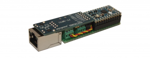
As you can see in the description the device offers a compact and easy to install enclosure (eg. using cable ties). The device solves the power feed issue through a simplified implementation of the PoE standard. The implementation solves too the installation issue in outdoor environments through a cheap and easy to built waterproof ruggedized PVC enclosure. The device is "plug and play" and it can be connected directly to the Internet access router (without any Gateway or additional adapter).
- Small footprint (85 x 20 x 15mm)
- Simplified PoE feed (typical length 20 mts)
- Cheap "off the shelf" components design
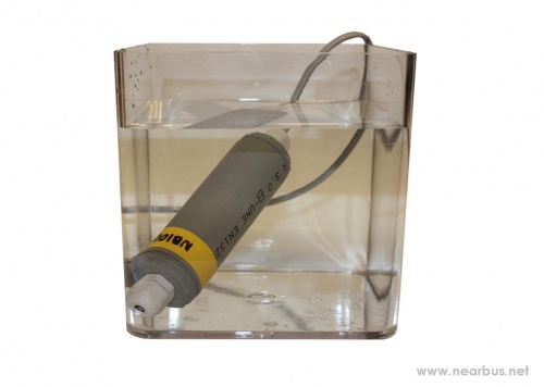
- Waterproof and ruggedized implementation (IP68 protection level [1])
The following picture shows a prototype sensor under a IP68 resistance test.
Components List
- Ethernet 28J60 Adapter - Where to Buy: [2]
- Arduino Mini - Where to Buy: [3]
- Ethernet Power Injector (pasive cable) - Where to Buy: [4]
- Arduino Nano option (All in One Kit) - Where to Buy: [5]
Waterproof Enclosure
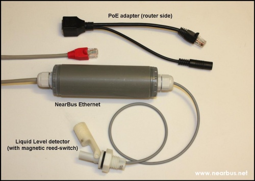
The following picture shows the device fully assembled. The full implementation require a passive PoE injector to feed the device from the router/switch. The picture shows the NearBus device working as a liquid level sensor.
Hardware Assembly
This picture shows the small footprint of this HW implementation. In order to obtain a waterproof and ruggedized enclosure it has been built using PVC pipe fittings and IP68 wire glands (components widely available on market).
Hardware Components
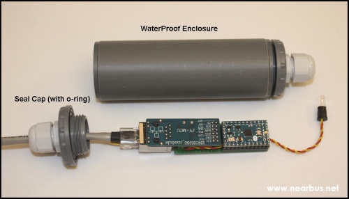
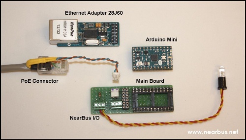
The following picture shows all the components used in this implementation. The base board is so simple that it could be implemented on a protoboard making some basic wiring.
The picture shows the sensor/actuator connection (yellow/red cable). In this example a LED has been used as "actuator" in order to test the system.
DOWNLOAD: To Download the NearBusEther28J60 code please go to the following link: [6]
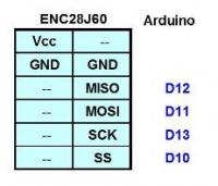
The wiring between the ECN28J10 and the Arduino is shown in the following table (it represents the ISP interface pinout). The system follows the usual NearBus I/O pins (Digital: 3-5-6-9 and Analog: 0-1-2-3)
The RJ45 ethernet connector require a special assembly in order to work as PoE system. As shown in the following picture the wires 4,5 and 7,8 should not be wired,they should be pull off (about 4 or 5 cm) from the RJ45 connector (not crimped) and connecting them directly to the main board.
This passive PoE implementation offers a typical resistance of 1 Ohm each 15 mts (if both power wires are working in parallel as required by the PoE standard).
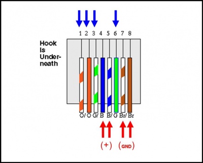
Nota: The picture shows the wiring color order that applies at both sides of the Ethernet cable (both RJ45 connectors).
For more information implementing this App Note please contact us at: info@nearbus.net