App Note 1220 - Cloud PLC
This App Note describes how to implement a Cloud PLC (Programmable Logic Controller), using the NearBus basic building components.
Contents
Overview
Note: The system described is not intended to replace an industrial PLC control system, however this basic architecture offers some PLC features than can be useful in experimental or non-critical applications.
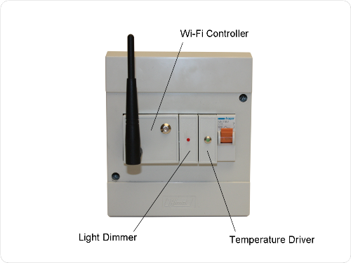
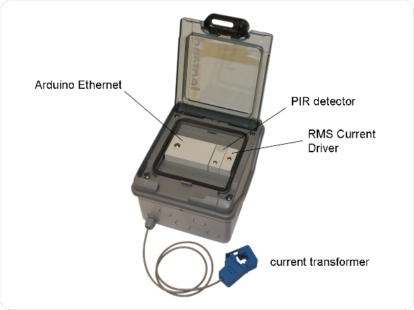
The cloud PLC architecture has been designed to be easy and cheap to implement (all the components used in the following examples are off-the-shelf components).
The main feature of this system is its standard industrial form factor. All components are designed to be implemented over a DIN rail mounting enclosure, and the circuits have been designed using off-the-shelf components.
For its implementation this app note needs some basics electronics skills and knowledge.
SYSTEM DESCRIPTION
The system has two main components, the Controller Module and the Drivers.
The Controller
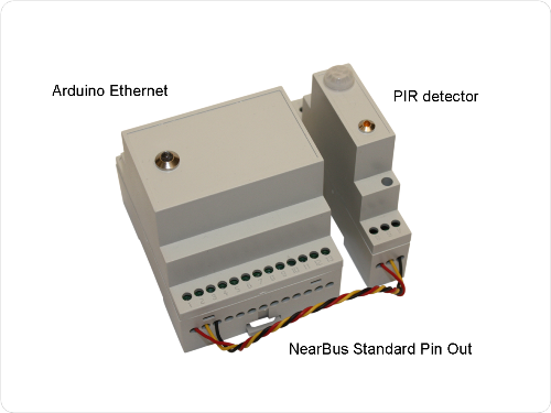
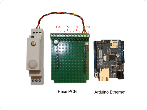
The controller is the main component in the Cloud PLC system. The controller consist basically of a microcontroller board (Arduino Ethernet for example), wired to a output following a NearBus typical pin-out.
The following picture shows a basic configuration example of a Controller module (Arduino Ethernet) and a standard PIR Driver
The Drivers
The drive modules are the electronic devices that make the adaptation function between the external signals and the microcontroller signals. Its functions include:
- To adapt the electrical levels.
- To isolate the microcontroller from dangerous signal levels (overtension, peak, etc.).
- To transform the I/O signals from/to different sensors or actuators to digital microprocessor compatible signals (digital or analog).
The drivers contain all the specific electronic needed to reach these functions. The electronic circuits have been designed to be cheap and easy to implement. They are mainly built using traditional analog electronic components (fully available in the market).
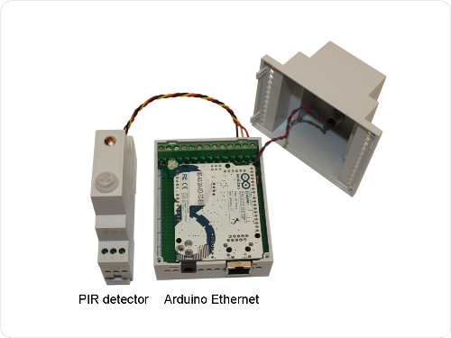
The following picture shows the basic support board and the NearBus pin-out assignment (note that each port represents only one microcontroller digital or analog I/O ) and a Vcc / GND connection (is important to remark than this 3 pin trivial configuration is enough for most of the practical implementations and offers a huge flexibilty at configuration time).
Remarks
The NearBus system has been designed as an open HW platform, under this philosophy each component in the NearBus project has been thought to be useful by itself.
For example the drivers in most of the cases are simple transducers that deliver a single signal to the controller (eg. temperature sensor) however they could be used alone in another system like feeding a conventional temperature display.
On the other hand the controller is basically an Arduino Ethernet board mounted into a DIN enclosure in order to simplify its mounting and wiring. This solution could be used for example with a conventional Arduino Uno board in standalone system that will not require a network connection (like an industrial data logger).
When needed we will include the circuit drawing in order to help you to understand how it works.
Dribvers List
The following list describes some of the main Drivers (sensors / transducers) that have been implemented in different NearBus scenarios.
| True RMS Current Meter (input) | Input |
| Power Dimmer | Output |
| Power Relay (output) | Output |
| Digital Input | Input |
| PWM Output (Servo Motor) | Output |
| Temperature Sensor - Lineal | Input |
| Temperature Sensor - Thermocouple | Input |
| Temperature Sensor - Termistor | Input |
| Energy Counter (pulse Counter) | Input |
| Infra Red Repeater (output) | Output |
| PIR Detector (input) | Input |
| Resistance Meter (input) | Input |
| RGB LED Controller (output) | Output |
| Anemometer (Wind Speed) | Input |
| Level Sensor (input) | Input |
| Position Switch Sensor | Input |
If you are interested in knowing more about this App Note please contact us at: info@nearbus.net
(*) This initial trial release has been deployed only for the Arduino Ethernet platform. We are deploying new Agent libraries for another Arduino boards and platforms with Ethernet and Wi-Fi connectivity.
