App Note 1252 - Xively Temperature Controller
This App Note introduces an experimental way to control the room temperature in a more efficient way.
Contents
Overview
This App Note is intended to show how to implement a simple Temperature Control System using the X-Controller NearBus feature. The system works under the NearBus paradigm, this means that every sensed signal will be transmitted to the Cloud for its processing. No processing is accomplished in the remote device that works in a transparent way, controlling the sensors and actuators through the NearBios functions
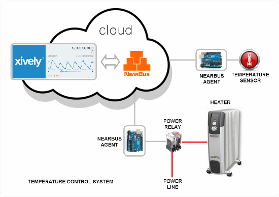
The following picture shows an implementation of a simple controller (using only one temperature sensor) using two Arduino boards.
Note: It is important to remark that under the NearBus architecture it is possible to implement this solution using another microcontroller platform in a transparent way (for example a Wi-Fi board in order to simplify the system deployment thanks to the Wi-Fi connectivity).
How does it work?
The system shown works as a traditional digital controller. The temperature sensor is sampled each 2000 ms for example (a configurable value) and feed it to a proportional controller (with hysteresis to avoid a flapping output). The controller compare the sensed signal with its internal setting and decides to turn on or off the electrical heater in order to maintain the room's temperature as near as possible to the configured value.
In this example we used two Arduino boards (one for the temperature sensor an another for the power relay) in order to show you the way in which the NearBus system works (of course it can be implemented using only one Arduino board).
Close Control Loop
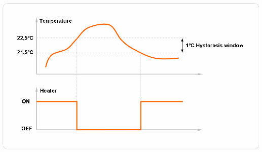
As a traditional control system this example works as a close control loop. The temperature is sensed at sampling time (eg. each 2000 ms) and then compared against the setting reference value (eg. 22 deg. C ). This resulting signal is used to control the power relay output. As usual in this type of ON/OFF controllers, a Deadban (hysteresis) module is mandatory in order to avoid a flapping output (eg. 1 deg. C).
System Components
The system is composed by three main components:
- The power switch: Arduino Ethernet/WiFi board + Relay driver
- The temperature sensor: Arduino Ethernet/WiFi + temperature sensor ( LM35 lineal IC)
- The NearBus X-Controller: An special NearBus feature that allows to interconnect remote devices using the Xively Cloud Infraestructure
X-CONTROL Configuration
TEMPERATURE SENSOR CONFIGURATION (INPUT)
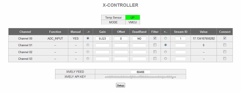
The following picture shows the X-CONTROL configuration for the temperature sensor device (Arduino Ethernet/WiFi). In this example we use a LM35 lineal Sensor [[1]] as temperature sensor (that offer an output of 10mV/ºC).
- Function: It shows the "DEVICE CONFIGURATION" screen configured function: ADC_INPUT (this option should be configured in the DEVICE CONFIGURATION screen for the specified device)
- Manual: It shows the "DEVICE CONFIGURATION" screen configured mode: MANUAL (this option should be configured in the DEVICE CONFIGURATION screen for the specified device)
- --> : This option configure the channel in "Device TO Xlively" mode (the sensed value will be sent to Xlively)
- Gain: A value of 0.323 is used (in this example) to adapt the read value to a Celsius value:
Gain Calculation Example
- ADC 10 bits (1023 steps)
- ADC Vref = 3300mV (3.3Vdc)
- Sensor LM35 10mV/ºC [[2]]

Gain = 3300mV / 1023 / 10mV/ºC = 0.323 ºC/step
- Offset: 0 (It doesn't apply)
- DeadBand: NO (this feature doesn't apply)
- Filter: Selected (in order to smooth the read signal)
- Stream ID: The Xively Stream ID (where the signal will be shareD with other NearBus device)signal)
POWER RELAY CONFIGURATION (OUTPUT)
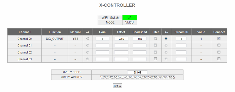
The following picture shows the X-CONTROL configuration for the Power Relay Control device (Arduino Ethernet/Wi-Fi).
- Function: It shows the "DEVICE CONFIGURATION" screen configured function: DIG_OUTPUT (this option should be configured in the DEVICE CONFIGURATION screen for the specified device)
- Manual: It shows the "DEVICE CONFIGURATION" screen configured mode: MANUAL (this option should be configured in the DEVICE CONFIGURATION screen for the specified device)
- <-- : This option configure the channel in "Xlively TO Device" mode (the processed value will be sent to the Device)
- Gain: 1 (there is no gain required in the stage)
- Offset: The Temperature set-point should be configured here (as negative value) in order to shape the signal before it be precessed by the Deadband function.
- DeadBand: The DeadBand value (1/2 of it) should be configured here. A negative value indicate that the output will be DOWN when the signal is raising, and it will be UP when the signal is decreasing (making stable the control system)
The following example explain how this function works: When the sensed signal drops below the bottom setting value in the Deadband function (below 21,5 deg. C) , the output will be UP (turning ON the heater). In turn when the temperature rises over the top setting value in the hysteresis block ( over 22,5 deg. C) the output will go DOWN (turning OFF the heater).
- Filter: NOT SELECTED (this feature doesn't apply)
- Stream ID: The Xively Stream ID (where the signal will be read)
XIVELY CHART EXAMPLE
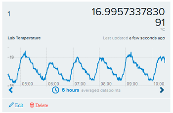
The following picture shows a real example on the Xively chart temperature register for a system working under a temperature set point of 18.5 ºC
