App Note #1227 - Room Temperature Controller
This App Note introduces an experimental way to control the room temperature in a more efficient way.
In contrast with the traditional system where the temperature is controlled by a local device, this system works under the NearBus paradigm, this means that every sensed signal will be transmitted to the Cloud for its processing. No processing is accomplished in the remote device that works in a transparent way, controlling the sensors and actuators through the NearBios functions
The following picture shows an implementation of a simple controller (using only one temperature sensor) using two Arduino Ethernet boards.
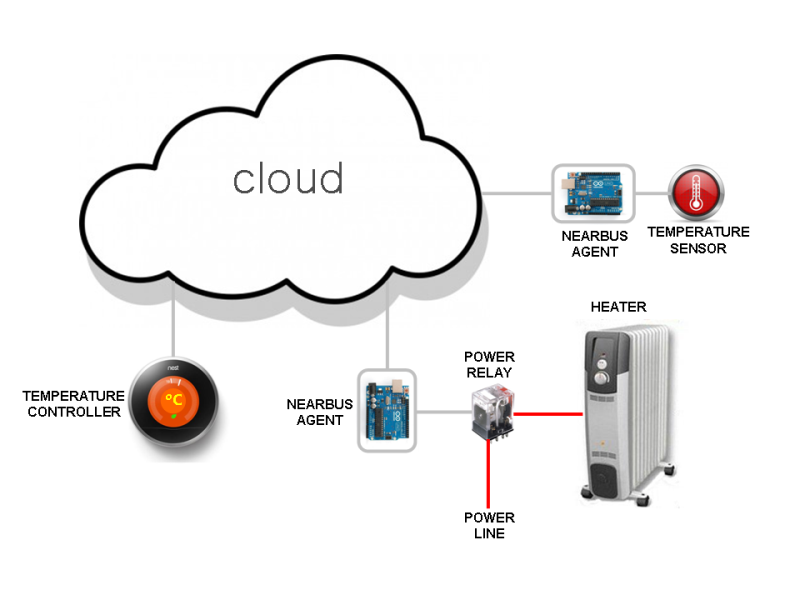
Note: It is important to remark that under the NearBus architecture it is possible to implement this solution using another microcontroller platform in a transparent way (for example a Wi-Fi board from OpenPicus in order to simplify the system deployment thanks to the Wi-Fi connectivity).
How does it work?
The system shown works as a traditional digital controller. The temperature sensor is sampled each 1000 ms for example (a configurable value) and fed it to a proportional controller (with hysteresis to avoid a flapping output). The controller compare the sensed signal with its internal setting and decides to turn on or off the electrical heater in order to maintain the room's temperature as near as possible to the configured value.
In this example we used two Arduino Ethernet boards (one for the temperature sensor an another for the power relay) in order to show you the way in which the NearBus system works (of course it can be implemented using only one Arduino Ethernet board).
Close Control Loop
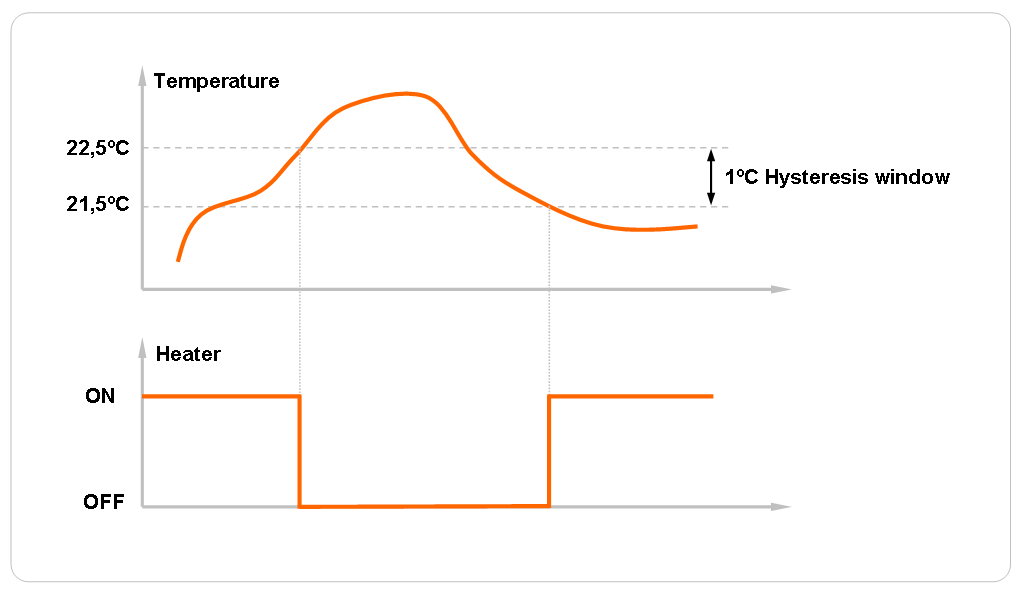
As a traditional control system this example works as a close control loop. The temperature is sensed at sampling time (eg. Each 1000 ms) and then compared against the setting reference value (eg. 22 deg. C ). This resulting signal is used to control the power relay output. As usual in this type of ON/OFF controllers, a hysteresis module is mandatory in order to avoid a flapping output (eg. 1 deg. C).
When the sensed signal drops below the bottom setting value in the hysteresis block (below 21,5 deg. C) , the output will be UP (turning ON the heater). In turn when the temperature rises over the top setting value in the hysteresis block ( over 22,5 deg. C) the output will go DOWN (turning OFF the heater).
System components
The system is composed by three main components:
- The power switch: Arduino Ethernet board + Relay driver
- The temperature sensor: Arduino Ethernet + temperature sensor ( LM35 lineal IC)
- The controller: a software code written in PHP and running over an Internet Apache Web Server.
The controller code basically consist of a simple state machine implemented into the PHP code working as a callback function. This function will be called each time that the remote temperature sensor updates a new value in the NearBus system.
System Benefits
Although this simple implementation of a temperature control system only has a demostrative value, the NearBus system offers some improvements when it is configured in a more complex way:
- PIR Detector: One of the main features of a NearBus architecture is that it allows to integrate additional sensors and actuators in an easy way. Adding a PIR sensor for example will enable the system to turn off (or reduce the setting temperature) when there are no people in the room.
- Spot Temperature Control: Another interesting feature is the ability to deploy multiple Wi-Fi temperature sensors and Wi-Fi heater switches, allowing to define different spot zones and control them in a more energy-efficient way.
If you are interested in knowing more about this App Note please contact us at: info@nearbus.net
(*) This initial trial release has been deployed only for the Arduino Ethernet platform. We are deploying new Agent libraries for another Arduino boards and platforms with Ethernet and Wi-Fi connectivity.