OVERVIEW - HELP
The next paragraphs describe the main features that NearBus offer to you, in order to allows you to configure, supervise and troubleshooting the remote devices connections.
INDEX
1 - Devices List
2 - Device Configuration
3 - New Device / Edit Device
4 - Device Statistics
5 - COSM Configuration (Pachube)
6 - Device Monitor
7 - REST API - VMCU Mode
8 - REST API - TRNSP Mode
If you are going to configure the Arduino Ethernet platform for the first time, please try the Hello World example.
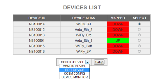
1 - Devices List
This screen shows you a list of all devices configured for your user account, allowing you to see quickly which devices are UP and wich are DOWN.
This screen shows you a list of all devices configured for your user account, allowing you to see in a fast way wich devices are UP and wich are DOWN.
From here you can access the following options for the selected device:
- Config Device: See the Device Configuration paragraph.
- Edit Device: See the New Device / Edit Device paragraph.
- Cosm Config: See COSM Configuration paragraph.
- Device Monitor: See Device Monitor paragraph.
2- Device Configuration
This screen allows you to set in manual mode each device and control the basic features of NearBIOS subsystem offers (this option is only available for channels 0 to 3):
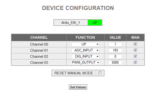
MAN (Manual Mode)
This check allows you to set each channel in Manual Mode (to control it with the function field)
Functions
Digital_IN: Digital Input ( 0 or 1)
Digital_OUT: Digital Output (0 or 1)
ADC_Input: 10 bits Analog Input (0 to 1023 for 0 to 1.1V). It uses the internal 1.1V reference
PWM_Output: Pulse width modulated output expressed in [us] and configured to control servo motors. The typical range for servo motors is from 800 to 2200 [us].
Note: The Pulse Counter function is not available in the actual release. If you need to implement a pulse output tranducer (like Flow meters or Energy meters) please contact us at info@nearbus.net.
Value
This field should be set with the desired value for output functions (DIG_OUT or PWM). When input functions are configured (DIG_IN or ADC)this field returns the read value.
Channel
The following chart shows how each Arduino's pin is mapped to the channels
Channel 0 = Dig_pin 3 + Analog A0
Channel 1 = Dig_pin 5 + Analog A1
Channel 2 = Dig_pin 6 + Analog A2
Channel 3 = Dig_pin 9 + Analog A3
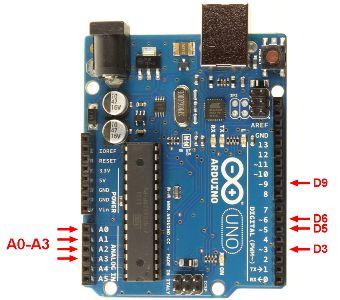
Note: It is possible to wire up the analog pins with the digital pins (because the analog pin are configured as inputs).
3- New Device / Edit Device
This screen allows you to create a new device (and delete it).
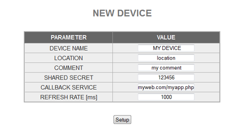
The main fields are:
- Device Name: Allows you to set a name ID for your new device (recomended)
- Location: Allows you to set the physical location (optional)
- Function: Allows you to set the device function (optional)
- Shared Secret: Set here the shared secret (mandatory length of 8). The same as you configured in the Arduino
- Callback Function: Allows you to define the web service (Back-End) that will work in a call-back mode.
- Refresh Rate: Allows you to set the pooling device period [ms]
The following fields are only showed in the Edit Device screen:
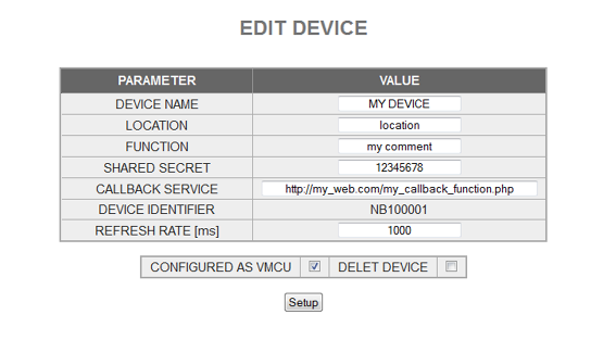
- Configured as VMCU: (default) Allows you to configure the VMCU mode (to control the MCU in manual mode)
- Delete Device: This option allows you to delete a device
- Device ID: It is a unique identifier for each device (NB1xxxxxx) that will be generated by the system (at configuration time and cannot be modified).
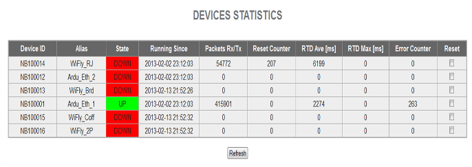
4- Device Statistics
This screen shows you the main statistics of each device (this feature is intended to be used in troubleshooting and system tuning).
5- COSM Configuration (Pachube)
This screen allows you send to Cosm the values received from or transmited to the remote device over each channel (this feature is intended to be used in troubleshooting and system tuning)
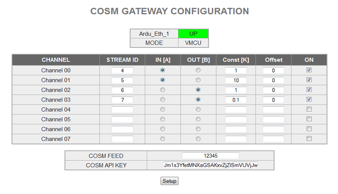
Stream ID
This field allows you to set the Cosm's datastream where you want to send the signal.
IN / OUT
This option allows you to indicate if you want to send a readed value (input) from the remote device or the written value (output) to the remote device for each channel.
Constant and Offset
The main advantage of this feature is that it allows you to apply a basic transfer function to your signal before sending it to cosm:
f(x) = x * K + offset
ON
This option allows you to turn on or off the data feed to Cosm.
Cosm Feed and API Key
This option allows you to configure the required parameters to connect succesfully to www.cosm.com.
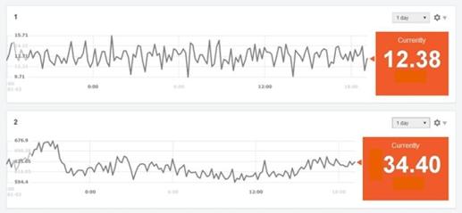
The following table shows an example of output sent to www.cosm.com (2 channels)
6- Device Monitor
This screen shows you the system data interchange for each device over the following interfaces:
NearHub <--> Device
NearApi <--> User App
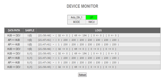
Note: this feature is intended to be used in troubleshooting and system tuning.
7- REST API - VMCU MODE
In order to offer the simplest interface the NearBus system offers a RESTful API to control the remote devices:
http://nearbus.net/v1/api_vmcu
As RESTful implementation the API uses the GET method to read values from the remote device (eg. Digital Inputs or ADC) and uses the POST method to write values to the remote device (eg. Digital Outputs a PWM).
Note: To improve the simplicity the NearBus system allows to use the GET method as a POST method adding the "method=POST" argument on the URL. This "feature" allows you to control your remote devices using the browser's address bar as a traditional command line interface (as shown below).
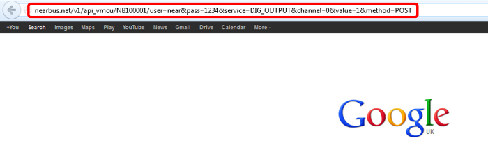
The following REST URL or command lines, show how to set to 1 the Channel 0, and to read the ADC value from the Channel 1 on the device NB100001.
Setting Up Channel 0:
http://nearbus.net/v1/api_vmcu/NB100001?user=nearbus&pass=1234&channel=1&service=DIG_OUTPUT&value=1&method=POST
Reading the ADC on Channel 1:
http://nearbus.net/v1/api_vmcu/NB100001?user=nearbus&pass=1234&channel=1&service=ADC_INPUT
Parameters
/device The device ID, like NB1xxxxxx
user= The same user as you use to login into the NearBus website
pass= The same password as you use to login into the NearBus website
channel= The remote agent's channel 0,1,2,3
service= The service to execute: DIG_INPUT, DIG_OUTPUT, ADC_INPUT, PWM_OUTPUT
value= The value to write, only required for DIG_OUTPUT, PWM_OUTPUT
method= POST, required to use the GET method as POST method
This release of NearBus support the following NerBIOS services (functions)
- DIG_INPUT: Digital Input (0 or 1)
- DIG_OUTPUT: Digital Output (0 or 1)
- ADC_INPUT: 10 bits Analog Input (0 to 1023 for 0 to 1.1V). It uses the internal 1.1V reference
- PWM_OUTPUT: Pulse width modulated output (it allows to control servo motors)
Note: If you want to debug the POST and GET method messages in a more detailed way, you can use the HURL web tool.
8- REST API - TRANSPARENT MODE
Probably the most powerful feature of NearBus system is the Transparent mode working with RTESful. Under this mode the system allows you to exchange up to eight 16 bits registers (int) in each system call.
The API URL is the following:
http://www.nearbus.net/v1/api_transp
This interchange or synchronization works as a simple function call that you can do from your Arduino sketch, as a traditional function call. There are 2 group of 8 (int) registers each ( rxChannel[ ] and txChannel[ ] ). The rxChannel[ ] is used to receive the data from the Cloud and the txChannel[ ] is used to send the data to the Cloud.
As you can see in the following example (to turn on and turn off the Arduino's pin 3), there is no change in the way in which the sketch is programmed. The only requirement is to set the txChannel[ ] registers, then call the Agente.NearChannel() function and finally process the received values in the rxChannel[ ].
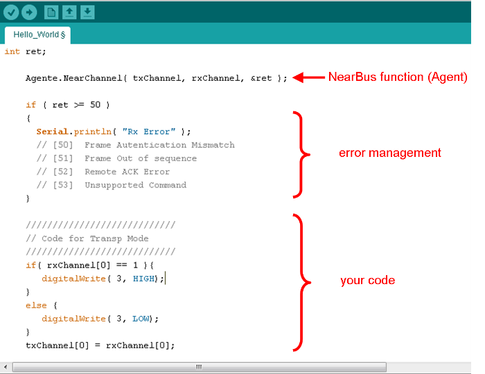
When calling the Agente.NearChannel() function, the data in the txChannel[ ] will be replicated in the NearHub data base Reg A (data from the Agent) and the rxChannel[ ] will be updated with a copy of the data in the NearHub data base Reg B (data to the Agent)
From the application point of view the data can be exchanged through the RESTful API calls, in a similar way as was shown in the VMCU mode.
The following examples shows the browser's command line (browser's address bar) that should be used to turn on and turn off the Arduino's pin 3 in the last example.
Turning ON the pin
http://nearbus.net/v1/api_transp/NB100001?user=nearbus&pass=1234&method=POST®00=1
Turning OFF the pin
http://nearbus.net/v1/api_transp/NB100001?user=nearbus&pass=1234&method=POST®00=0
Note: In order to simplify the example the unused registers have been avoided (the transp_api supports this syntax). The full example to turn on the pin should be:
http://nearbus.net/v1/api_transp/NB100001?user=nearbus&pass=1234&method=POST®00=1®01=0®02=0®03=0®04=0®05=0®06=0®07=0
If you are interested in trying the NearAPI please contact us at: info@nearbus.net
This initial trial release has been deployed only for the Arduino platform. We are deploying new Agent libraries for other platforms.